solar setup on the gypsy wagon
On Saturday, I went to Mateo's place and we installed a photovoltaic module on my vehicle. He has a drill and a garage full of tools!
Before you ask, no this is not to power the drivetrain. (Why does everybody assume that? Scientific illiteracy I guess...) This is to provide an additional auxiliary power circuit in the vehicle to, eg, charge my mobile devices when camping/travelling.
First, the equipment list (some of this we had to get the day of after re-evaluating my original design).
The main hardware:
- 1x EcoFlow 100W Rigid Solar Panel with mounting brackets and charging cable
- EcoFlow RIVER 2 power station
- 2x 1-1/4in x 4ft zinc-plated slotted angle 14-gauge steel rails
- 4x 1-1/4in 10-32 JIS-head machine screws
- 8x steel washers (size = whatever, it fits)
- 8x shallow 10-32 nuts (would have gone with 4 larger/deeper ones but this was all they had at the hardware store near Mateo's place)
- 1x 2-gland ABS conduit
- electrical tape
- some splicing twist caps that will fit a 12AWG cable
- RED threadlock
- FLEX CAULK (clear)
Supporting cast:
- a drill and a phat steel bit for penetrating the roof of the vehicle
- wire strippers
- a good light source
- a ladder
- screwdriver
- pliers
step 1: yolo
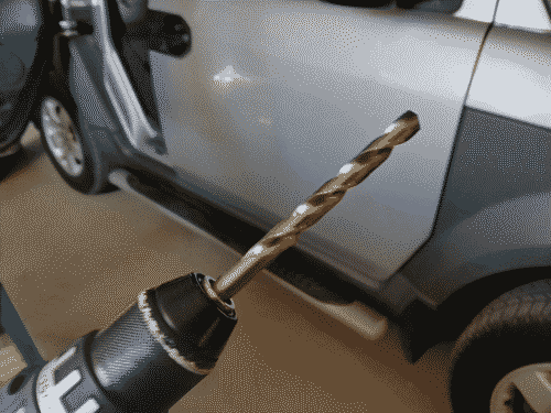
First thing was drilling a hole in the roof of the vehicle. On the element, there are two layers of steel as well as a layer of plastic and a bunch of insulation between the plastic and inner steel layers. Good luck making it all the way through in a straight line. Once you get through the first steel layer, check and make sure you aren't drilling through the frame or any wiring.
step 2: splice & route
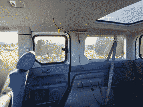
Because the glands on the conduit are too small for the solar connectors or the XC60 connector on the charging cable to fit through, we had to splice. Routing the spliced cables through the hole in the roof was ironically the most challenging part of the whole project. This is where the good light source comes in - have somebody shine the light up from below with some forceps or pliers ready while you route the cables from above so you can see what you're doing.
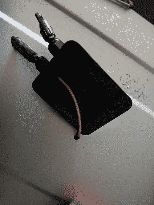
Once the cables were through the roof, we cleaned all the metal shavings off it and used the Flex Caulk to seal the conduit onto the roof. Then, inside the vehicle, we joined the cables back together with both the twist caps and the electrical tape.
step 3: test the panel
This is important. I bought 2 panels with the power supply as a bundle, but my final design only used one (more on that below). Before starting to mount the panel, I put each one in place on top of the vehicle and connected it to the power bank to measure the output via the integrated LCD. One panel got about 5W more than the other, so I used that one.
step 4: attach the mounting feet
My original design actually did away with the mounting feet, but that was under the assumption I would use both of the panels mounted widthwise one behind the other. After doing calculations based on the limitations of the power bank and the fact that the panels would be right next to each other, I decided the gains from 2 panels would be negligible compared to the complexity and aerodynamic implications of mounting them that way.
So, we attached the mounting feet on the length of the panel. Very important here is the red threadlock. If you don't apply it for this kind of automotive work you're gonna have a bad time.
step 5: clamp it
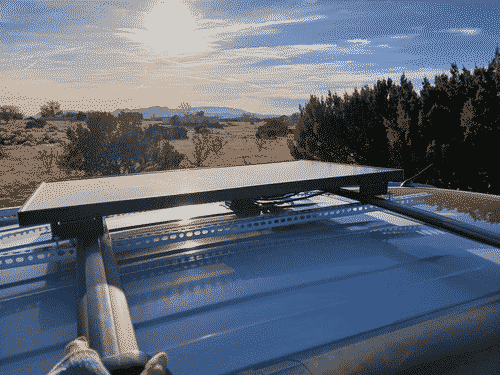
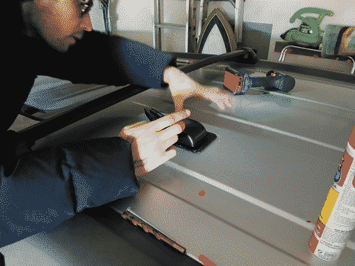
After putting the panel on the roof and plugging it into the charging cable, comes the moment of truth! We ran the steel rails under the luggage rack and bolted the mounting feet to them. We used the washers to help ease some of the stress on the rails and mounting feet, and due to the fact I could only find these low-depth nuts I used 2 of them on each bolt to increase the overall force they could withstand. Again, the threadlock here is crucial so it all stays together. Placement is all the way on the right side of the vehicle as opposed to in the center, so I can mount a container on the left side in the future if I want to.
Using a phillips screwdriver and a pair of pliers, we tightened it all down after bleeding the threadlock into the nuts, using the amount of exposed thread on the bolts below the nuts to gauge the clamping force on all 4 corners was roughly equal.
step 6: send it
After some high fives and hugs, it was time for me to head back home. I was extremely nervous driving on the highway from Mateo's place back to Santa Fe, having read a horror story of somebody's panel ripping right through its aluminium frame from the lift force generated driving at highway speeds. The design is holding so far. I'm not sure if mounting the panel lengthwise has anything to do with it. Reading on the "complete" explanation of lift force on wikipedia seems to suggest the horror story I read might have had something to do with the angle of attack.
If I notice any degredation of the clamp force in the coming days I will probably get another set of rails and run them above the mounting feet with more bolts running along the length of the rails to distribute the clamping force more. Any updates to the setup will be reflected here with another syndication to the honknet. Anyone who didn't effectively drop out of classical mechanics feel free to tell me if I'm being stupid please <3
postscript
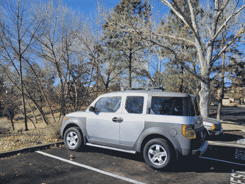
6000 miles later and it held up great.
